Products 
MICURA
Maximum Precision for Small Parts

ZEISS MICURA sets the standard in the compact class. Despite its small size, ZEISS MICURA makes no compromises when it comes to accuracy. ZEISS MICURA comes standard with the VAST XT gold scanning sensor from ZEISS and navigator technology.
  • Introduction
  • Available Software
  • Available Sensors
  • Solutions
Small and precise
ZEISS MICURA is the solution for new demands in industrial production where parts are becoming increasingly compact and accuracy requirements are rising. Equipped with the VAST XT gold high-end sensor from ZEISS and navigator technology, ZEISS MICURA offers active scanning with measuring accuracy of less than one micrometer. ZEISS MICURA flexes its muscles, in particular, with small, complex parts featuring narrow tolerances such as those used in optics and electronics. Despite its compact size, this system provides a measuring volume of 500 x 500 x 500 millimeters – and therefore considerably more than comparable instruments.
 
Precise high-speed scanning
The VAST XT gold sensor from ZEISS enables high-speed scanning featuring up to 200 measuring points per second. As a result, form and location parameters such as roundness and flatness can be precisely captured, in addition to geometric features, in a short time. The sensor can be equipped with extremely small stylus tips. The smallest stylus has a diameter of just 0.3 millimeters.
 
Automatic measuring speed with VAST navigator from ZEISS
ZEISS MICURA comes standard with VAST navigator technology. It automatically configures the optimal measuring speed with guaranteed accuracy, thus considerably reducing the measuring time. ZEISS MICURA moves somewhat slower in areas that demand more precision. It moves faster with simple contours or when less accuracy is needed. navigator technology also saves time through tangential approach and scanning, helix scanning and fast dynamic stylus calibration.
 
Computer-Aided Accuracy (CAA)
Measuring errors due to dynamically induced inertia effects are automatically compensated for.
 
Operation and ergonomics
ZEISS MICURA comes with a redesigned control panel. One display and two joysticks enable operators to control and program the machine independently of the computer. The system is easy to operate and makes it possible to start measuring even without in-depth experience with measuring machines. The ledge on the front of the granite table allows the control panel and tools to be stored outside the measuring range.
 
Well thought-out design
Ø     Ceramic guideways and a large bearing base minimize susceptibility to external influences
Ø     ZEISS air bearings on four sides guarantee stability and precision
Ø     ZEISS MICURA also comes with a temperature sensor for the workpiece
Ø     The probing force of the sensor is actively regulated and is very low - ideal for sensitive materials
Ø     Controller technology, software, sensors and additional components are made by ZEISS and are finely tuned to each other
 
Sample applications
Ø     Converters and adjusting units with highly accurate leads and bearings
Ø     Pistons and shafts with the tightest tolerances
Ø     Artificial hips
Ø     Gear wheels
Ø     Optical lens elements
CALYPSO——The total program for standard geometries and more
 
Ø    Many tasks – one tool
CALYPSO is designed for manual and CNC measurements, online and offline programming. CALYPSO is multisensor capable and supports all current sensors and measuring capabilities from Carl Zeiss. Via the I++ DME interface, CALYPSO allows you to control non-ZEISS measuring systems such as 3D measuring machines, articulated arm measuring machines, laser trackers and computer tomographs.
 
Ø    Collision-free – automatically
As soon as you define a part feature and the associated tolerances with a few clicks of the mouse, CALYPSO automatically generates an appropriate measuring strategy that can be modified and applied to other features at any time. CALYPSO quickly moves the stylus around the workpiece without collisions and approaches the part features correctly – you are free to deal with other tasks.
 
Ø    Dynamic mini-plan
CALYPSO’s hierarchical design and feature-oriented programming give you the flexibility to focus your measurement planning on the production process. For example, you can interrupt measuring runs to quickly measure another part. The interrupted measurement can be easily continued afterwards. More intelligent scanning with VAST Navigator CALYPSO supports VAST Navigator – the fifth generation of scanning from Carl Zeiss. Without unnecessary interruptions and with optimal approach and travel paths, VAST Navigator allows you to measure smoothly in one run. A tangential approach is standard. Fully integrated intelligence enables CALYPSO to determine the maximum scanning speed depending on the required accuracy.
 
Optional interfaces: IGES 2D/3D, VDA 2D/3D, STEP 3D, DXF 2D, PMI, and FTA can be directly processed.
Optional direct interfaces: ParaSolid, CATIA V4, CATIA V5, ProEngineer, UniGraphics, Inventor, Solid Works
 
CALYPSO options——Extension: Tools for Special Jobs
 
Ø    CALYPSO curve
Measure and calculate 2D and 3D curves. Inspection features: curve slope, cam throw, curve length, curve form, surface area, etc. Fields of application: crankshafts, cam shafts, turbine blades, powertrains.
 
Ø    CALYPSO freeform surfaces
Measurement of freeform surfaces. Deviations from plan are marked in color. Typical fields of application include medical technology, moldmaking and engine construction in which freeform surfaces have to be inspected along with standard geometries.
 
Ø    CALYPSO preset
Preset erosion electrodes and processing tools. Users are graphically guided through the manual measuring run. The most commonly used measurement plans are saved. CNC extensions are available for square and round basic geometries.
 
Ø    CALYPSO PCM
Menu-guided control of parameter-supported measuring runs. Workpiece variations can be efficiently measured using a measurement plan parameterized with CALYPSO PCM.
 
Ø    myCALYPSO
myCALYPSO turns your measuring machine into a flexible gage. Standard measuring tasks, such as the measurement of the interior diameter or height, are saved as macros and can be loaded with a few clicks of the mouse.
 
Ø    CALYPSO simulation
Virtual collision observation. The part, clamping equipment, stylus, probe, base plate, rotary table, measuring range, or the entire measuring machine, are simulated in the CAD window. In conjunction with CALYPSO planner, measuring runs can be generated and simulated remotely.
 
Ø    CALYPSO/qs-STAT export
Export measuring results in the Q-DAS format for analysis in the qs-STAT statistics program. CALYPSO qs-STAT export converts the CALYPSO result files from a CNC measuring run into Q-DAS description and value files. With qs-STAT, you can then statistically evaluate production processes, for example.
 
Ø    CALYPSO planner
The offline version of CALYPSO. Use CALYPSO planner to write measuring programs offline. Your measuring machine is not blocked by CALYPSO planner and can continue being used for additional measurements. CALYPSO planner saves the finished measuring program. Furthermore, it can be loaded and run at any time with CALYPSO. In conjunction with CALYPSO simulation, measuring runs can be generated and simulated remotely.
 
Ø    FACS automation
FACS (Flexible Automation and Control System) is used to integrate the measurement cells into CIM automation environments. FACS establishes the connection between the measuring cell and the process control computer. This allows you to initiate measuring runs from a customer-specific user interface.
 Ø     RDS——The basis for maximum flexibility
The RDS articulating probe holder is particularly well-suited for measuring complex parts, where features require many styli with different spatial directions. It reaches up to 20,736 positions in 2.5-degree increments – thus providing access to every part feature. This is made possible by the horizontally and perpendicularly arranged rotary axes with rotational ranges of plus/minus 180 degrees.
Furthermore, the RDS-CAA for touch-trigger and measuring sensors leads to shorter calibration times: only a few spatial angular positions require calibration. During programming, the RDS can be easily positioned using the joystick on the control panel to enable shorter programming times. Designs are available for machines in standard, compact and multisensor configurations.
 
Ø     VAST XT gold——All systems go for active scanning
VAST XT gold features an additional measuring system. The measuring force can be configured depending on the measuring job. It is also used for a line of correction procedures.
In addition to active scanning, this sensor also allows single-point measurements: for example, the sensor enables the flexible use of complex stylus configurations and self-centering.
Thanks to its high-speed scanning capabilities, VAST XT gold can complete practically any job: form and position measurements, curve and freeform measurements, and reverse engineering. The applications cover plastic machined parts and Styrofoam, brake components, crankshafts, engine blocks and turbine blades.
 
Ø    VAST XXT——Scanning done differently
There are a large number of measuring applications that can benefit from the flexibility of an articulating probe holder combined with scanning capability. VAST XXT is ideal for such tasks.
Compared to touch-trigger sensors, VAST XXT increases the operational safety and accuracy of the measurements. It also adds scanning functionality, thus providing information on the form of the features.
The compact design of lightweight scanning sensors on the articulating probe holder requires different sensor modules. With only three modules, VAST XXT covers the typical stylus length ranges for this sensor design. This sensor accommodates lateral styli up to 65 millimeters. It is also suitable for fixed installation.
 
Ø    ViScan——Spotlight on two dimensions
The hallmark of ViScan is its flexibility in all aspects: combined with RDS, it permits measurements in all spatial directions without rechucking the part. Different lenses are also available. The working distance is practically independent of the lens used, thus allowing the measurement of deep features. In addition to the measurement in the image, the auto-focus system also permits measurements perpendicular to the camera plane.
ViScan is particularly well-suited for the measurement of parts with very small or two-dimensional geometries and/or soft materials such as sheet metal, rubber or plastic parts. Difficult measurements can also be performed on low-contrast test pieces such as punched components or printed circuit boards using the optional, mobile transmitted light stages with LED illumination.
 
Ø    LineScan——Point clouds at the speed of light
LineScan is extremely fast: up to 250,000 points per second can be captured for high-speed digitizing. The short measuring times lead to a considerable increase in productivity. CALYPSO measuring software and the automatic sensor change out on machines featuring MASS technology also contribute to the high productivity of this sensor. The accuracy also increases thanks to the definable point grids and consolidation possibilities for intelligent point reduction.
The LineScan optical sensor is the tool of choice, particularly for car bodies, mold/tool making, construction and design, as well as for contact-sensitive or finely structured surfaces.
 
Ø    XDT——Precision in all probing directions
There are many instances when users require the flexibility of an articulating probe holder. In place of touch-trigger sensors, the XDT enables in increase in the operating safety and accuracy of the measurements.
Unlike touch-trigger single-point measuring, singlepoint scanning with sliding acquisition of measuring points provides a result featuring maximum accuracy and reliability. With “single-point scanning,” the measuring point is measured with at least 100 measuring points. Outliers are no longer important, considerably improved accuracy is guaranteed.
High Precision Optics
——Optics manufacturer decreases part failure rate by 30 percent with ZEISS CMM
 
As Rochester Precision Optics (RPO) knows all too well, optical component manufacturing requires high accuracy inspection with a delicate touch. A recent expansion in production and an increasing demand for faster throughput and improved part quality made the search for the right quality inspection equipment much more important.
 
The situation
RPO, located in West Henrietta, New York, recently added 43,000 square feet of space to their existing 64,500 square foot headquarters building in February 2012. This expansion facilitates the increased demand of their comprehensive design and manufacturing capabilities for rapid prototyping and high volume production of lenses, assemblies and sub-assemblies. For quality inspection, RPO had been using various gages, optical systems and various manual tools. They now needed a CMM (coordinate measuring machine) to give them the higher accuracy and increased measuring throughput to meet new customer requirements.
 
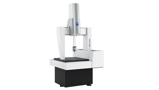
Right solution for small, intricate parts
RPO chose the MICURA bridge-type CMM from Carl Zeiss Industrial Metrology. “Accuracy was our main concern, but the MICURA was also the right fit for measuring our small, intricate parts,” states Nick Gennarino, manager of Quality at Rochester Precision Optics. The compact MICURA 5/5/5 with VAST XT gold active scanning sensor is designed to provide submicron accuracy and low probing force with high-speed scanning rates of up to 200 points per second.
 
In addition to incoming, in-process, and final inspection, RPO uses the ZEISS CMM for first article inspection and design research. The most common components they measure are the metal or plastic barrels which will contain the lenses and are about 2 to 4 inches long. First, the material is machined to the required tolerances for various diameters, undercuts, grooves and threads. That is followed by the initial inspection on the CMM. Once the part is accepted, the lot will move through production, with machinists performing in-process checks with hand tools and carrying out periodic checks on the CMM. After the lot is completed, final inspections are done on the MICURA before and after the parts have been plated by a 3rd party. It’s critical to monitor part dimensions closely before and after the plating process because of the inherent risks of dimensional changes resulting from the plating process. Pre-plate dimensions are correlated with post-plate dimensions to better control the final product, improve efficiency and reduce waste. “You have to know what you’re putting into the plating process so you can expect good parts out of it,” states Nick. Once all of that is complete, they move to the assembly department. Targeted tolerances range from 3 to 10 microns and they currently measure about 40 barrels per week.
 
Reduced part failure rate
After a few short months, RPO noticed increased throughput along with a significant part failure rate reduction. A big challenge with the aluminum barrel inspection was meeting the required tight tolerance dimensions before the parts went out for plating. With the ability to check the barrels on the MICURA before and after plating, the part failure rate has been reduced from 30 percent to zero. “For us, that was huge,” says Nick. And on one particular barrel, a 13-piece inspection period was reduced from 8 hours to 2 hours. This increased throughput allows RPO to inspect even more part types now.
 
In addition to increased accuracy and speed, the MICURA has brought new inspection opportunities to RPO. Molds for glass lenses, from another department within RPO, can now be measured in house. Mold profiles can now be checked for the accuracy and precision needed to provide meaningful information to discover mold issues that they can now correct. “We can drill down to the micron, and see everything if we need to,” remarks James Keene, mechanical inspector / programmer at RPO. They have also been able to understand their parts and processes better, and see how part material is changing. “It’s amazing to see how much material can grow, shrink, or warp,” states Joe Hennigan, mechanical inspector / programmer at RPO.
 
About the company
Rochester Precision Optics (RPO) was formed in 2005 when it acquired the manufacturing technology, intellectual property and assets from Kodak Optical Imaging Systems. Starting production in 2006 and building on its core technology of precision molded glass aspheres, RPO has grown from 27 employees to over 190 today.